CrOwBX build notes
(last updated 2017-07)

I've built completely from the silkscreen, and here are the changes/decisions I've made so far for my four-voice system, based on discoveries in the Muffs thread and my own findings.
http://www.muffwiggler.com/forum/viewtopic.php?t=83363

Host board:
-----------
Rewired R93 and R94 to correct the Osc1 mod / Osc2 mod destinations - as described in host board BOM document
R22 change: from a 33K to a 4K7
R23 change: from a 33K to a 4K7
Omitted italic parts listed in host board BOM, installed R164/R165/R166
3296Z type used for trimmers R83/R132/R133/R143
Mute switch not fitted - floating is apparently fine
Made noise generator PIC using clone Pickit3 from ebay and MPLAB X software. I had a 12F675 IC and used the Electric Druid white noise generator code.
(remember to choose 'Power from programmer' in the project settings 'power' section)


Carrier board:
--------------
Removed R34/R158 (both 15K) for clipping diodes to work properly
3296Y type used for distortion trimmers R29/R52 - could maybe use 3362?


Slot adaptor board:
-------------------
No jumpers, fully populated otherwise.
I'm not particularly fussed about stereo output so might swap the 3296Z panning trimmers for 3362 if the boards fit tight.


Voice board:
------------
R1/R2/R3/R4 all 0.1%

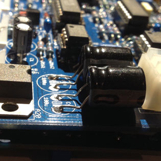
C1/C2 would be better as short (<5mm high) caps. I used 7mm high ones with the wrong lead pitch and had to bend them over the nearby resistors

C4 will clash with the 3296Z 50k trimmers on the slot adaptor board above - leave leads long and bend them over to lie flush with the board in the space below the GG connector.

C49 should be a short cap, otherwise bend a 7mm cap over into the space above

R165 change: from a 27K to a 33K (to match the schematic)

Omit R158 for polyphonic setups as detailed on schematic

3362 type for all trimmers apart from T1/T4/T7/T8/T9/T10, which are 3296Z multiturn.

T1/T4/T9/T10 are mounted on the solder side of the board to enable adjustment from the side and back when all cards are mounted.

T1/T4 apparently supposed to be 100K not 10K (silkscreen says 10K) - not confirmed.

Multiturn probably not necessary for T9/T10 - but getting access via the side/back is a real boon when matching voicecards.

I initially bought some bigger 3386 trimmers by mistake - they'll fit for a few positions - T2/T5/T3/T6/T11/R150/R151 but I wouldn't recommend using them.

Place R168/R177 together before soldering.

Q21/Q22/Q25 change: from 2N3906 to 2N3905 - possible fix for high resonance lock-up issue.

I seemed to be very unlucky with my CD4052 chips - envelope problems across all voices (for example zero decay or release time, or an envelope never starting) were cured by trying many different parts.
It may be that the envelope circuit demands high-tolerance parts and that some ancient or out of spec parts will exhibit switching problems.
I had issues with some Harris and TI parts.
--
Important finding that may disprove the above theory: I noticed that the carrier board can flex significantly downwards depending on how the voice adaptors are forced in.
This could mean that certain pins on the D and E connectors are not seated and therefore not passing control voltages from the host board correctly.
This may explain why some envelope parameters were not correct.

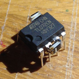
Clamping diodes on A11 - inverse parallel pairs across pins 2/3 and across pins 5/6. Done this by stacking pairs of 1206 SMD 4148 diodes on the tops of the IC legs. Effectiveness: unknown :)

Spacing between cards 1/2 and cards 3/4 - 17.5mm
Spacing between cards 2/3 - 23.5mm


External to CrOwBX
------------------

My enclosure plan is a 4U main panel, in a 200mm deep 4U metal rack case. I intend to mount a few extra modules on the front panel. I bought a black 4U blank and have drilled it out.
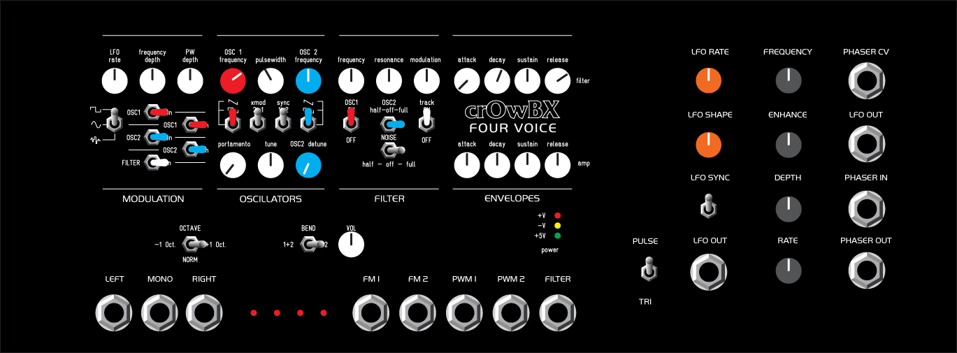
I think I'll be adding a paperface legend of some kind when it's all working.

If I could start again I'd strongly consider mounting the controls off board. Everything is compact and perfectly usable as it stands but if all the controls were spread over a 19" rack panel it would be so much nicer.

I'm using an Oakley PSU, powered by a Yamaha PA-20 line-lump supply. The Oakley PSU can be easily trimmed to give out +/-19V when using this Yamaha supply.
I have mounted the PSU parallel to another 4U blank rack panel. Hopefully this 3mm thick panel with drilled holes will provide enough of a heatsink for the PSU.
This panel will fit to the rear of the 4U rack case - 200mm is tight so the PSU is mounted to the right hand side of the case, the CrOwBX to the left.

I have built a small stripboard circuit using 7815 and 7915 regulators to step the +/-19V down to +/-15V, which I will need for the following extra modules:

- Hexinverter/ACXSynth 4-channel MIDI/CV converter
- Oakley Little LFO (for extra modulation - I'm not keen on the internal sine LFO and would rather have a triangle)
- Oakley Equinoxe VC phaser (I have one in a drawer since I upgraded to a Deep Equinoxe...)
Power for those will be distributed via half of a CGS74 0.156" power bus.

The PSU heatsink isn't getting remotely hot with host/carrier/4x slot/voice and the MIDI/CV. Nice comfortable warmth coming from the voice card regulators though :)


Hexinverter/ACXSynth MIDICV
---------------------------

This is a very suitable module for MIDIing-up a four-voice CrOwBX.
As of 2017 it doesn't seem to be available as a DIY project any more, but the schematics are still around and alternative firmware is available.

I have not used the front panel or panel PCB from this project. Instead I have directly wired the CV/gate pairs to CrOwBX.
The stock firmware as it stands will not do round-robin voice allocation. First key pressed will always use Voice 1 etc. New firmware will sort this.

2017:
I used the Quokka alternative firmware. It needs a different PIC (PIC16F1847) but as of June 2017 this works perfecly for CrOwBX using the Poly1 mode.
It provides an easy way to calibrate each octave using MIDI. This goes some way to offset the non-linearity in the 12-bit DACs.
It's not absoutely perfect (0.01-0.02V out on some notes), but it's close enough and certainly what I want from an analogue polysynth.
Sadly this firmware doesn't do unison (e.g. same CV/gate to all four voices). I can see a way how to do this, but currently can't get it to compile.
To do
-----

Decide on panel extras - whether to route control signals with switches or jacks

Investigate how to implement switchable unison and remain compatible with MIDI/CV

Don't really like the sine LFO for either PWM or pitch. Investigate using the triangle wave at R157.

Lay out a 2164-based VCA board for Osc2 pitch control via FEG. This will allow for classic sync-sweeps and other interesting effects.
(Alternatively order Crow's filter expansion board if a proper wiring guide ever surfaces.)


Other info
----------
http://www.cs80.com/crowbx/ - Crow's main project site and store.
http://www.muffwiggler.com/forum/viewtopic.php?t=83363 - epic Muffwiggler build thread.
http://electricdruid.net/white-noise-source/ - Electric Druid noise source PIC project.
https://www.dsl-man.de/display/DSO/Obx+-+Building+Tips - LED-man's build guide.
https://www.oshpark.com/shared_projects/wlcvd0ji - this is Crow's filter expansion board that fits into the A13 socket. No wiring info provided yet.
https://bitbucket.org/tkoi/midi2cv - alternative Quokka firmware for the Hexinverter Midi2CV module.


